
Nexus Dashboard Orchestrator
- Mukesh Chanderia

- May 16, 2024
- 9 min read
Updated: Dec 9, 2025
Step 1: Log into ND

click --> ok

Step 2: Go to Dashboard it will take you to One View display

Step 3: Go to Admin Console

Step 4: configure a route for the out-of-band access to your site.
Go to Infrastructure >Cluster Configuration. In the Routes area, click Edit (the pencil symbol), choose Add Management Network Routes, enter 192.168.11.0/24, confirm it, and click Save.

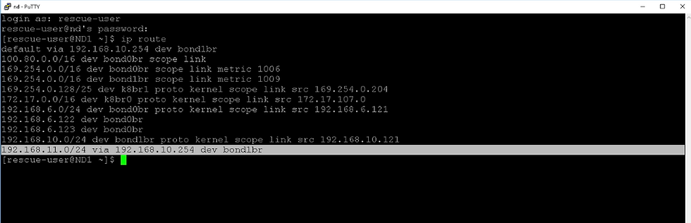
Log in putty in ND and you must see management route
Step 5: Add Site
Click on site

Add site


Step 6: Go to Services and open the Nexus Dashboard Orchestrator.


Step 7: In the Orchestrator, go to Infrastructure > Sites. Set the state of the HQ site to Managed. Configure the Site ID 1 and click Add.


Step 8: Refresh the page, click the three dots on the right (details symbol) and choose Import Tenants. Choose the tenant Sales and click OK

A schema is used to push a policy to multiple sites. Having imported the tenant Sales, you have not imported its sub-policies. In this scenario, you will create another tenant Support, define several sub-policies, and push the new tenant to the site.
Schema contains Templates & displays tenants associated with it.
A Template can be associated to one or more site
Schema you first need to select tenants & then App Profile, EPG, VRF, BD and contract, filter & External EPG.
Any policy change made to template will always be applied and pushed at one time to all the sites associated with template.
So, if you want to stretch VRF but not BD you need different template
Template 1: VRF pushed to both site
Template 2: BD – subnet pushed to site 1 only
Template 3: BD – subnet Pushed to site 2 only
Step 9: Go to Application Management > Tenants,

Step 10: Tenants, click Add Tenant, set the display name to Support, make sure it is associated with site HQ and click Save.

Step 11: Go to Application Management >Schemas, click Add schema, enter its name Support-Schema and click Add.


Step 12: In the TEMPLATES menu, click the Add symbol, set the template type to ACI Multi-cloud and click Add.

Step 13: In the right pane, set the Display Name to Support-Template and select tenant Support.

Step 14: In the middle pane, hover your mouse over Application profile and click Add Application Profile.
In the right pane, enter the display name Support_AP.

Step 15: Hover your mouse over EPGs and click Add EPG. In the right pane, enter Front_EPG as the display name for the EPG.

Step 16: Hover your mouse over VRFs and click Add VRF. Set the display name to Support_VRF.

Later, when you push the template to your site, you will see that the display names actually become the object names.
Step 17: Hover your mouse over Bridge Domains and click Add Bridge Domain. Set the display name to Support_BD.Select Support_VRF from the Virtual Routing & Forwarding drop-down list.

Step 18: Click the Front_EPG and select Support_BD from the Bridge Domain drop-down in the right pane & click "Save"

Step 19: In the navigation pane, click + in the SITES menu. Check HQ, choose the Support-Template and click Save.

Step 20: In the top-right corner, click Save. In the middle pane, click Deploy to sites. Then click Deploy and close schema configuration page.

Step 21: Go to Infrastructure > Sites, open the HQ details by clicking on the three dots and choose Open in APIC user interface.

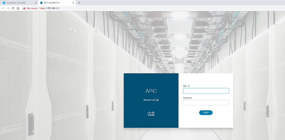
In a nearby tab APIC GUI will open
Step 22: Check the Tenant "Support" has been provisioned with MSO


Configure Fabric Connectivity Infra
Step 23: Return to the Orchestrator, go to Infrastructure > Infra Configuration and choose Configure Infra.

Step 24 : Review the parameters in General Settings > Control Plane BGP.

Default is full-mesh but can be configured as "route-reflector"

Step 25: General Settings > IPN Devices.

Step 26 : Choose the HQ site in the navigation pane and the click outer square in the middle pane, containing site-level settings. In the right pane, in Overlay Configuration, click the ACI Multi-Site knob to enable the site for Multi-Site connectivity and configure these settings:
Overlay Multicast TEP: 10.10.10.10
External Routed Domain: ExtL3Dom
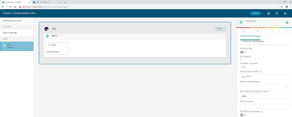

The BGP AS number is the same one as MP-BGP AS and is automatically pulled from the Cisco APIC.
The Overlay Multicast TEP is used as the outer IP for VXLAN encapsulation when another site sends a flood traffic towards this site. When this site receives the packet with this outer IP, it will treat it as flooding traffic. Hence, the Overlay Multicast TEP itself should be a unicast IP address that is routable within ISN.
Step 27 : In the right pane, choose Underlay Configuration and configure the following settings:
OSPF Area ID: 1
OSPF Area Type: regular

Open Shortest Path First (OSPF) is to establish an OSPF session with the ISN device, which needs to be manually configured. OSPF is used to advertise the Overlay Multicast TEP to the ISN.
Step 28 : Select pod-1 (intermediate square in the middle pane) and set the Overlay Unicast TEP to 192.168.50.1


Overlay Unicast TEP is used as the outer IP for VXLAN encapsulation when another site sends a unicast traffic to this pod in this site. Each pod needs a specific Overlay Unicast TEP IP address.
Step 29 :
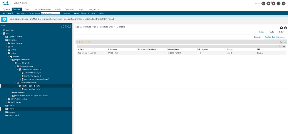
Select spine (inner square in the middle pane), click Add Port and enter these parameters for the OSPF spine peering. Click Save.
Ethernet Port ID: 1/5
IP Address: 172.30.1.1/30
MTU: 9216
OSPF Policy: msc-ospf-policy-default
OSPF Authentication: none


Within the spine settings, click the BGP peering knob to enable BGP-EVPN and set the BGP-EVPN router ID to 10.7.7.7. Click Deploy in the top task bar.

Step 30 : Go to the Cisco APIC user interface, navigate to Tenants > infra > Networking > L3Outs. Expand the L3Out intersite and examine its sub-elements.
Note : The switch profile and spine interface profile for this Multi-Site configuration have not been automatically added to the external domain ExtL3Dom. In production environments, configure those policies to keep the fabric fault-free.
Step 31 : Within the infra tenant, go to Policies > Protocol > Fabric Ext Connection Policies > Fabric Ext Connection Policy and briefly examine the policy.

A pod connection profile "1" has been provisioned. Other specific options, such as fabric external routing profiles have not been pushed. This validation completes the lab exercise.
ACI Multi-Site and L3Out Shared GOLF L3Out.
GOLF configuration (‘infra’ tenant L3Out) performed on APIC.
Tenant L3Outs locally provisioned on each site’s APIC
Multi-Site associates Golf L3Out from each site with App OpenCart

Multisite Translation Requirements
In a typical APIC multisite environment, a particular site may expose certain services which other sites may desire to consume.
An example would be a shared DNS service provided by one of the sites which other sites want to use.
The other common use case is to allow peer-to-peer communication between a pair of EPgs across sites.
pod36-leaf1# show system internal epm endpoint ip 172.16.2.2
MAC : 0050.56b1.4403 ::: Num IPs : 1
IP# 0 : 172.16.2.2 ::: IP# 0 flags :
Vlan id : 21 ::: Vlan vnid : 8194 ::: VRF name : DC:DC1
BD vnid : 16220082 ::: VRF vnid : 2457600
Phy If : 0x1a001000 ::: Tunnel If : 0
Interface : Ethernet1/2
Flags : 0x80004c04 ::: sclass : 32771 ::: Ref count : 5
EP Create Timestamp : 04/19/2018 07:03:23.999543
EP Update Timestamp : 05/02/2018 02:33:29.507208
EP Flags : local|IP|MAC|sclass|timer|
pod36-spine1# show coop internal info ip-db key 2457600 172.16.2.2 : <-- local site
IP address : 172.16.2.2
Vrf : 2457600
Flags : 0
EP bd vnid : 16220082
EP mac : 00:50:56:B1:44:03
Publisher Id : 10.1.48.64
Record timestamp : 05 02 2018 02:29:12 339899902
Publish timestamp : 05 02 2018 02:29:12 340145880
Seq No: 0
Remote publish timestamp: 01 01 1970 00:00:00 0
URIB Tunnel Info
Num tunnels : 1
pod35-spine1# show coop internal info ip-db | egrep -A 15 -B 1 "172.16.2.2$" <-- Remote Site
------------------------------
IP address : 172.16.2.2
Vrf : 3014656
Flags : 0x4
EP bd vnid : 15925206
EP mac : 00:50:56:B1:44:03
Publisher Id : 10.10.35.102
Record timestamp : 01 01 1970 00:00:00 0
Publish timestamp : 01 01 1970 00:00:00 0
Seq No: 0
Remote publish timestamp: 04 24 2018 05:05:34 611613733
URIB Tunnel Info
Num tunnels : 1
Tunnel address : 10.10.35.102
Tunnel ref count : 1
Tunnel address : 10.1.48.64
Tunnel ref count : 1
-----------------------------------------------------------------------------------------------------------------
Understanding NDO (Nexus Dashboard Orchestrator): Sites, Schemas, Templates & Deployment Workflow
Cisco Nexus Dashboard Orchestrator (NDO) provides centralised automation for multi-site ACI fabrics.However, the GUI has two places where "Sites" appear:
Orchestrator → Operate → Sites
Admin Console → Operate → Sites
These two lists do NOT show the same information, and their purpose is different.
This article explains:
The difference between the two “Sites” views
The exact workflow to build and deploy configuration
How Schemas, Templates, Tenants and Sites relate
Let's begin.
1. Difference Between Sites in “Orchestrator” vs “Admin Console”
A. Sites shown under Admin Console
Path: Admin Console → Operate → Sites
This page shows Nexus Dashboard (ND) Cluster Inventory, not ACI sites.
It displays:
Each ND cluster’s own metadata
Cluster health
What services (Orchestrator, Insights, Fabric Controller) are enabled
Firmware versions of the ND cluster itself
Local system resources
Local service health (Pods, containers)
👉 This list does NOT represent the ACI managed sites.
It is ND platform-level information.
B. Sites shown under Orchestrator
Path: Orchestrator (MSO/NDO) → Operate → Sites
This is the actual list of all ACI APIC Fabrics onboarded into Orchestrator.
Each entry shows:
APIC cluster name
Site ID
Connectivity (green/yellow/red)
APIC firmware version
State (Managed / Discovered)
👉 This is the real list of ACI sites where configuration will be pushed.
These are the sites that templates are deployed to.
✔ Summary Table
Feature | Admin Console → Sites | Orchestrator → Sites |
Purpose | ND Cluster management | ACI Multi-Site orchestration |
Shows | ND Clusters | APIC Fabrics |
Used for Templates | ❌ No | ✔ Yes |
Affects ACI Deployment | ❌ No | ✔ Yes |
Deployment Target | ❌ Not applicable | ✔ These sites |
2. NDO Configuration Architecture
NDO uses a top-down hierarchical design:
Schema
→ Templates
→ Tenant
→ Objects (VRF, BD, EPG, Contracts…)
→ Site Association
→ Deployment
Let’s understand each component clearly.
3. What is a Schema?
A Schema is the top-level container for organizing templates.
Each schema can contain 1 or more templates
Schemas do NOT deploy anything by themselves
They exist only to logically group templates
Example schemas:
BS-CLOUD
PROD-APP
KKM-Schema
A schema is created under:
Configure → Tenant Templates → Add Schema
4. What is a Template?
Templates are the real working units inside a schema.
Each template has:
One tenant
Multiple objects (VRF, BD, EPG, L3Out, Contracts…)
One or more associated sites
Its own version history
Templates define what configuration will be deployed and where.
5. Tenant Association (IMPORTANT)
When creating a template:
→ You must select a tenant→ This tenant will be created on all associated sites (if not already existing)
A template cannot exist without a tenant.
The tenant determines the entire scope of that template.
6. Site Association (CRITICAL)
Each template must be associated with one or more ACI APIC sites.
This defines:
Which fabric(s) will receive the configuration
Whether the configuration is local or stretched
✔ Examples:
Template Type | Sites Associated | Behavior |
Local Template | Site A only | Tenant & objects deployed only to Site A |
Stretched Template | Site A + Site B | VRF, BD, EPG etc. stretched across fabrics |
Multi-Site Template | Site A + Site B + Site C | Same tenant deployed across multiple fabrics |
7. Step-by-Step End-to-End Workflow
Here is the exact recommended workflow:
STEP 1 — Onboard APIC Sites into Orchestrator
Path: Orchestrator → Operate → Sites → Add Site
Verify:
Connectivity = Green
Version detection correct
Status = Managed
STEP 2 — Create a Schema
Path: Configure → Tenant Templates → Add Schema
Provide:
Schema name
Optional description
👉 A schema is just a container — no configuration yet.
STEP 3 — Add a Template Inside the Schema
Path: Schema → Add Template
Provide:
Template name
Select Tenant Name
Select Template Type (Application / Networking / Stretched etc.)
This links the configuration to a specific tenant.
STEP 4 — Associate Template with Sites
Inside the template:
→ Click Associate Sites
Select:
One or multiple APIC sites
This defines where your template will be deployed.
STEP 5 — Create Objects (Inside the Template)
Examples:
Create VRF
Create Bridge Domain
Create Subnet
Create Application Profile
Create EPG
Create Filter
Create Contract
Create L3Out
All of these must be created inside the template, not at schema level.
STEP 6 — Deploy Template
Click:
Deploy TemplateorDeploy Out of Sync Templates
NDO will:
Validate dependencies
Push the configuration to all associated sites
Update template status to In Sync
STEP 7 — Verify Deployment
Check:
Template Status = In Sync
Site Count = In Sync
APIC → Tenant → VRF/BD/EPG matches expected state
Optional STEP 8 — Use Version History / Rollback
View differences between versions
Roll back to previous versions if needed
Re-deploy after rollback
NDO and APIC
1. Understanding NDO’s Object Ownership Model
NDO does not function as a “real-time mirror” of everything configured on APIC.Instead, NDO manages only the objects that:
Were created in NDO, and
Were pushed to APIC by NDO.
Anything configured manually on APIC is considered APIC-local configuration.
This includes:
Static Path Bindings
Static Leaf Assignments
VLAN Encap Bindings
Domain Attachment
Interface/Port selector mappings
These APIC-local objects are not imported into NDO, even if the site shows In Sync.
2. Why “In Sync” Doesn’t Mean What You Think
Many engineers assume that In Sync means APIC and NDO have identical configuration.
This is not true.
In Sync = “APIC has accepted everything NDO pushed.”
It does not verify:
Whether local changes were made on APIC
Whether APIC has additional static ports
Whether path bindings exist only locally
Whether interface selections match the template
Therefore, it’s entirely possible for:
APIC to have 50+ static ports
NDO to show zero static ports
Site status to still be In Sync
This is expected behavior.
Comments