Service Graph
- Mukesh Chanderia

- Feb 24, 2024
- 4 min read
Updated: Sep 26, 2024
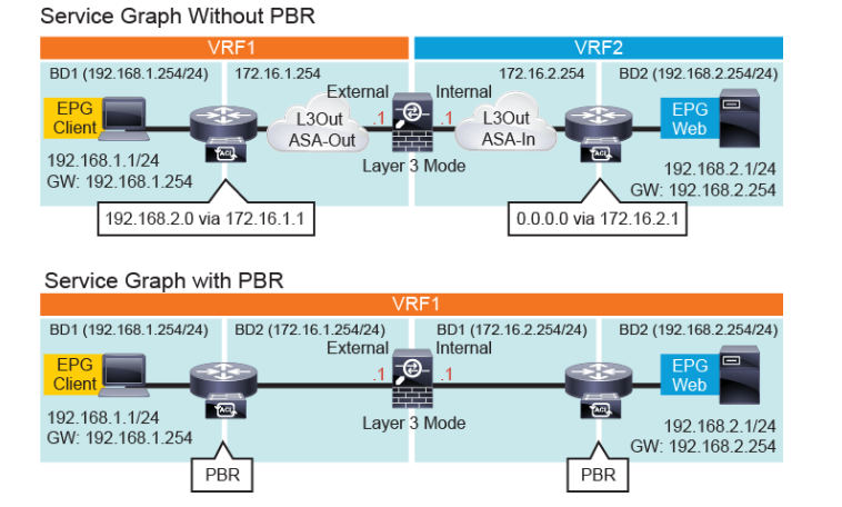
Service Graph with PBR and without PBR
The design that uses service graph without PBR requires multiple VRFs.
The use of service graph with PBR significantly simplifies the configuration using a single VRF.
The following figure depicts three deployment options for insertion of a perimeter firewall in routed mode, which protects north-south traffic flows between the external Layer 3 network and the web EPG.
The first choice involves employing the firewall as the gateway for the server of the web EPG. The server operates within a bridge domain, directing all inter-subnet traffic through the firewall, thereby utilizing firewall resources.
The second option employs the Cisco ACI fabric as the gateway. In this setup, not all inter-subnet traffic is routed through the firewall, as doing so requires additional configurations like VRFs and L3Outs to direct traffic through the firewall.
The third option leverages a service graph with Policy-Based Routing (PBR), enabling selective redirection of traffic, while utilizing the Cisco ACI fabric as the gateway.
Cisco ACI service graph with PBR can be used in different scenarios while inserting service nodes, including the following:
Insertion of firewalls or load balancers in the path between endpoints, while keeping the default gateway on the Cisco ACI fabric.
Insertion of a Layer 4 to Layer 7 device in the path between endpoints that are in the same subnet.
Selectively separating traffic that is based on protocol and port filtering that is sent to Layer 4 to Layer 7 devices.
Service Graph PBR Configuration
The configuration items include creation of the Layer 4 Layer 7 service device, a service graph template, Layer 4 to Layer 7 PBR policy for the consumer/provider connector, and application of the service graph template to the EPGs with a contract along with the PBR policies.
On the menu bar, choose Tenants > tenant_name.
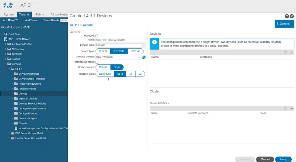
In the Navigation pane of the chosen tenant, choose Services > L4-L7 > Devices
In the Work pane, choose Actions > Create L4-L7 Devices.
In the Create L4-L7 Devices dialog box, complete the fields as required, such as Name and Service Type, which can be Firewall or ADC in the General section, create external and internal concrete interfaces and port connectivity on the corresponding leaf switches, and so on.
In the Navigation pane, choose Tenant > tenant_name > Services > L4-L7 > Service Graph Templates.
In the Work pane, choose Action > Create L4-L7 Service Graph Template.
In the Create L4-L7 Service Graph Template dialog box, perform the following actions:
In the Service Graph Name field, enter a name for the service graph template
For the Graph Type radio buttons, click New Graph.
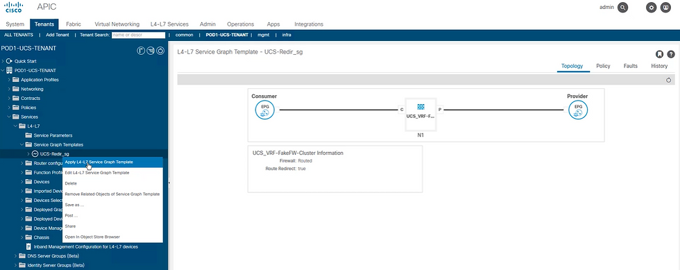
Drag and drop the device that you created from the Device Clusters pane to between the consumer EPG and provider EPG. By drag and dropping, you create the service node.
For the Firewall radio buttons, click Routed. Note Choose the Transparent option from the Firewall radio buttons, when the inserted firewall performs transparent inspection of the redirected traffic such as Layer 1/Layer 2 PBR.
In the Profile drop-down list, select a function profile appropriate to the device. If no profiles exist, create one.
Check the Routed Redirect check box and click Submit.
In the Navigation pane, choose Tenant > tenant_name > Policies > Protocol Policies > L4-L7 Policy-Based Redirect.
In the Work pane, choose Action > Create L4-L7 Policy-Based Redirect to create PBR policy for the consumer connector.
In the Create L4-L7 Policy-Based Redirect dialog box, complete the fields as required, including L3 destinations to specify packet rewrite information, so the leaf node will know to which destination MAC address it should send the packet during traffic redirect.
Create another PBR policy for the provider connector.
In the Navigation pane, choose Tenant > tenant_name > Services > L4-L7 > Service Graph Templates > service_graph_template_name and choose the service graph template that you just created.
Right-click the service graph template and choose Apply L4-L7 Service Graph Template.
In the Apply L4-L7 Service Graph Template to EPGs dialog box, perform the following actions:
In the Consumer EPG/External Network drop-down list, choose the consumer EPG.
In the Provider EPG/External Network drop-down list, choose the provider EPG.
For the Contract Type radio buttons, click New Contract.
In the Contract Name field, enter a name for the contract.
Uncheck the No Filter (Allow All Traffic) check box.
On the Filter Entries table, click (+) to add an entry, specifying "IP" for the Name and choose IP for the Ether Type, click Update, and then click Next to finish step 1 and move to step 2.
For the Consumer Connector BD drop-down list, choose the bridge domain that connects to the consumer EPG. The bridge domain must have IP learning disabled.
For the Consumer Connector Redirect Policy drop-down list, choose the redirect policy that you created for the consumer connector.
For the Consumer Connector Cluster Interface drop-down list, choose the consumer cluster interface.
For the Provider Connector BD drop-down list, choose the internal bridge domain that connects to the provider EPG. The bridge domain must have IP learning disabled.
For the Provider Connector Redirect Policy drop-down list, choose the redirect policy that you created for the provider connector.
For the Provider Connector Cluster Interface drop-down list, choose the provider cluster interface, and click Finish.
-------------------------------------------------------------------------------------------------------------------------------
Create IPSLA monitoring policy
2. Create L4-L7 Redirect Health Group
3. Create L4-L7 Policy-Based Redirect
4. Create L4-L7 device
5. Create Service Graph Template
Drag Fw in between Consumer & Provider EPG
6. Now apply the L4-L7 Service Graph template


Comments