
Transit Routing in ACI
- Mukesh Chanderia

- Nov 21, 2023
- 10 min read
Updated: Feb 11
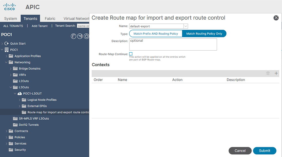
Default-export route profile with a prefix-list in the L3Out.

In this scenario, the Legacy router must establish communication with the subnet 172.16.1.0/30, located behind the Partner Router, via the Cisco ACI fabric.
The Cisco ACI fabric must seamlessly advertise and export the subnet 172.16.1.0/30, learned from the L3Out Partner, to the L3Out Legacy, enabling smooth and efficient routing across the network infrastructure.
The above objective can be achieved by two ways.
Option 1 - "default-export" Route Profile
Go to Tenant(POC1) --> Networking --> L3Outs --> L3Out (POC1-L3OUT) --> Route map for import and export route control --> Right Click --> Create Route map for import and export route control --> select "default-export"

select "Match Routing Policy Only"
The Two Route Map Types
You see two options:
1️⃣ Match Prefix AND Routing Policy
2️⃣ Match Routing Policy Only
This is critical for transit design.
Match Prefix AND Routing Policy
This means:
ACI will evaluate:
1️⃣ L3Out Subnet Scope (Export/Import Route Control Subnet)AND
2️⃣ Route Map match conditions
Both must match for route to pass.
This can create unexpected filtering if you:
Configure subnet scope
Configure route map
Forget one of them
Match Routing Policy Only
This means:
ACI ignores L3Out subnet scopes.
Only the route-map match rules apply.
This is why in transit-heavy environments this option is preferred:
You are essentially telling ACI:
“Do not merge with subnet scopes. Only follow this route map.”
Now on Contexts --> click on "+"


Configuring the "Default-Export" Route Profile
1. Application of "Default-Export" Route Profile
Direct Application:
The “default-export” route profile is applied directly to the L3Out.
No Association Needed:
It does not need to be associated with the L3Out Endpoint Group (EPG) to take effect.
2. Configuring Additional Parameters
Centralized Configuration:
When using the "default-export" route profile, any additional parameters for the advertised routes can be set within the same "default-export" route profile.
Flexibility:
This allows for comprehensive and centralized management of route advertisement settings without needing multiple profiles.
3. Advertising Multiple Subnets to Legacy Router
Scenario Overview:
Multiple Subnets:
Several subnets are received from the Partner Router.
Advertisement Requirement:
These subnets need to be advertised to the Legacy Router.
Configuration Steps:
Define Prefix-List:
Create a prefix-list with the 0.0.0.0/0 prefix.
Use Aggregate Option:
Apply the Aggregate option within the prefix-list.
This consolidates multiple subnets into a single aggregated route, simplifying the advertisement process.
Benefits:
Efficiency:
Reduces the complexity of managing multiple individual route advertisements.
Scalability:
Facilitates easier scalability as more subnets are added from the Partner Router.
Option 2: "Export Route Control Subnet" Scope with L3Out Subnets
Adding Extra Settings to Advertised Routes
When to Use a Route Profile:
If you need to add extra details, like BGP communities, to the routes you advertise.
Recommended Configuration Steps:
Create a New Route Profile:
Choose a Unique Name: Don’t use the default name "default-export."
Set the Type: Select "Match Prefix AND Routing Policy."
Apply the Route Profile:
To the L3Out Subnet:
Use the "Export Route Control Subnet" setting.
Or to the L3Out EPG:
Directly attach the route profile to the Endpoint Group (EPG).
Go to External EPG created under L3Out
Under Policy --> General --> click on "+" on subnet
Let's Understand the crucial terms
1. Export Route Control Subnet
Purpose:
Controls what ACI advertises out to the external routers via BGP, OSPF, or static redistribution.
Use When:
You want ACI to advertise this subnet (usually a Bridge Domain subnet or static route) to external peers.
Think:
“I want to EXPORT this subnet to the outside world.”
2. Import Route Control Subnet
Purpose:
Controls what ACI accepts from external routing peers and installs into its routing table (MP-BGP RIB).
Use When:
You want ACI to learn and import external prefixes (from the router into the fabric) so that internal workloads can route to them.
Think:
“I want to IMPORT this route into ACI.”
3. Shared Route Control Subnet
Purpose:
Used when you want to share learned external routes between VRFs inside ACI (requires VRF route leaking).
Use When:
You’re doing VRF route leaking (i.e., sharing routes between two VRFs in ACI).
Typically used with route maps and export policies in shared services scenarios.
Think:
“I want to SHARE this route across VRFs in ACI.”
4. External Subnet for External EPG
Purpose:
Used to define which external subnets can talk to internal workloads via contract-based policy enforcement.
Use When:
You want to allow communication from outside (router) into ACI based on policy.
Defines which traffic is matched against EPG contracts.
Think:
“This subnet is allowed to talk to my workloads via the contract.”
No policy contract = no communication, even if the route is learned.
5. Shared Security Import Subnet
Purpose:
Allows external EPG subnets to be used in policy enforcement across VRFs, not just the one it was learned in.
Use When:
You want to allow traffic across VRFs and enforce contract-based security between tenants or VRFs.
Think:
“I want this external subnet to be allowed and secured across VRFs.”
Feature | Affects | Direction | What It Actually Controls |
Export Route Control Subnet | Routing (Control Plane) | Outbound | Marks prefixes eligible for advertisement from ACI to external routers (requires Export Enforcement) |
Import Route Control Subnet | Routing (Control Plane) | Inbound | Filters which external routes ACI installs in the VRF (requires Import Enforcement) |
Shared Route Control Subnet | Routing (Control Plane) | Internal (VRF-to-VRF) | Marks prefixes eligible for route leaking between VRFs (requires Shared L3Out configuration) |
External Subnet for External EPG | Security (Data Plane) | Classification | Classifies external traffic into an External EPG so contracts can be enforced (no routing impact) |
Shared Security Import Subnet | Security (Data Plane) | Internal (Cross-VRF) | Extends External EPG classification (pcTag) across VRFs to allow cross-VRF contract enforcement |
Control-plane scopes determine whether the route exists.
Data-plane scopes determine whether traffic is permitted.
Requirement | Control Plane | Data Plane |
Route present | Import Route Control | — |
Route leaked | Shared Route Control | — |
Traffic allowed | — | External EPG Subnet + Contract |
Cross-VRF allowed | — | Shared Security Import + Contract |
Aggregate Export:
Purpose: Used to advertise all routes (export) externally for the default route (0.0.0.0/0).
How it Works:
It must be enabled with "Export Route Control Subnet".
When both options are enabled, a prefix-list "0.0.0.0/0 le 32" is created, matching every possible subnet.
Usage Note:
This is ideal when you want the L3Out to advertise any and all routes to external devices.
For more specific route advertisement, use a Route Map or Profile with a custom prefix-list.
Aggregate Import:
Purpose: Used to learn (import) all routes from external sources for the default route (0.0.0.0/0).
How it Works:
It must be enabled with "Import Route Control Subnet".
When both options are enabled, a prefix-list "0.0.0.0/0 le 32" is created, matching every possible subnet.
Usage Note:
This is useful when you need the L3Out to accept any route from outside.
The same outcome can be achieved by disabling "Import Route Control Enforcement" (which is the default).
For more precise route importation, use a Route Map or Profile with a custom prefix-list.
Aggregate Shared Routes:
Purpose: Used for aggregating shared routes for any specific subnet range.
How it Works:
It is used in combination with "Shared Route Control Subnet".
For example, if enabled for the subnet 10.0.0.0/8, it creates a prefix-list "10.0.0.0/8 le 32".
Usage Note:
This prefix-list will match the entire range (e.g., 10.0.0.0/8, 10.1.0.0/16, etc.), effectively aggregating shared routes within that range.


Similary add 172.16.100.100/32 also as "Export Route Control Subnet"
If there are several subnets than use "Aggregate" option.


Now add 172.16.200.200/32 as "External Subnet for the External EPG" (checkmark this option & uncheck export route control subnet).
L3Out EPG needs to define the external subnet that belongs to itself via the scope "External Subnets for the External EPG."
The End Result will be as follows :

And

Important Points regarding L3Out
A (logical) node profile is used to identify the leaf switch that is connected to external networks, and that should deploy the routing protocol or static routes towards it.
If you want to configure static routes then it will be on Node Profile.
Logical Node Profile Configured Nodes tolpology /pod-1/node-102

A (logical) interface profile, in this case a switch virtual interface (SVI), is used to identify the L3Out interface that connects to the external device.

If you click on L3out , it will show how many BD it has been called by clicking “BD’s Reference in”

You may find “L3 Domain” for L3out in L3Out_Name --> Policy --> Main

To check which ip is being configured on Leaf switch
leaf-b# show ip ospf interface vrf Sales:Presales_VRF
Vlan20 is up, line protocol is up
IP address 172.16.1.1/30, Process ID default VRF Sales:Presales_VRF, area backbone
Enabled by interface configuration
State BDR, Network type BROADCAST, cost 4
Index 73, Transmit delay 1 sec, Router Priority 1
Designated Router ID: 172.16.100.100, address: 172.16.1.2
Backup Designated Router ID: 10.1.1.1, address: 172.16.1.1
1 Neighbors, flooding to 1, adjacent with 1
Timer intervals: Hello 10, Dead 40, Wait 40, Retransmit 5
Hello timer due in 00:00:03
No authentication
Number of opaque link LSAs: 0, checksum sum 0
To check ip address configured on other side
leaf-b# show ip ospf neighbors vrf Sales:Presales_VRF
OSPF Process ID default VRF Sales:Presales_VRF
Total number of neighbors: 1
Neighbor ID Pri State Up Time Address Interface
172.16.100.100 1 FULL/DR 17:52:55 172.16.1.2 Vlan28 (This is PI vlan & not encap)
The L3Out Domain can be seen at following path
L3Out --> Policy --> Main

BGP Peer Connectivity Profile (a sub-element of the interface profile) contains provides options to Set next-hop Self , Disable Peer AS check , Send Community and to set Local and Remote AS.
L3_Out --> Logical Interface Profile --> BGP_L3Out_interfaceProfile

To See all BGP routes (irrespective of present in routing table)
Leaf # show bgp vpnv4 unicast vrf Sales:Presales_VRF & show bgp ipv4 unicast vrf Sales:Presales_VRF
Note : Above both commands contains equivalent information but the route distinguisher is stripped from the reachability information.
Leaf # show bgp sessions vrf Sales:Presales_VRF
L3 Out Transit Lab
L3 Out Transit
-----------------------------------------------------------------------------------------------------------
We are using Nexus Switch to Simulate as endpoint.
On doing "show lldp neighbour"
leaf1 Eth1/5 --> Nexus Port 120 BR Eth1/15 (Leaf 1 port)
leaf5 Eth1/24 --> Nexus Port 120 BR Eth1/14 (Leaf 5 port)
-------------------------------------------------------------------------------------------------------------
Let's check config on Nexus ports
Eth1/5
interface Ethernet1/5
no switchport
vrf member ISP1
ip address 10.0.0.2/24
ip ospf network point-to-point
ip ospf mtu-ignore
ip router ospf 1 area 0.0.0.0
no shutdown
n9k# show run vrf ISP1
interface Ethernet1/5
vrf member ISP1
vrf context ISP1
router ospf 1
vrf ISP1
Now add loopback interface
interface loopback101
vrf member ISP1
ip address 101.101.101.1/32
ip ospf network point-to-point
ip router ospf 1 area 0.0.0.0
interface loopback102
vrf member ISP1
ip address 102.102.102.1/32
ip ospf network point-to-point
ip router ospf 1 area 0.0.0.0
n9k# show ip interface brief vrf ISP1
IP Interface Status for VRF "ISP1"(53)
Interface IP Address Interface Status
Lo101 101.101.101.1 protocol-up/link-up/admin-up
Lo102 102.102.102.1 protocol-up/link-up/admin-up
Eth1/5 10.0.0.2 protocol-up/link-up/admin-up
--------------------------------------------------------------------------------------------------
Eth1/24
interface Ethernet1/24
no switchport
vrf member ISP2
ip address 172.16.0.2/24
ip ospf network point-to-point
ip ospf mtu-ignore
ip router ospf 1 area 0.0.0.0
no shutdown
n9k# show run vrf ISP2
interface Ethernet1/24
vrf member ISP2
vrf context ISP2
router ospf 1
vrf ISP2
interface loopback201
vrf member ISP2
ip address 201.201.201.1/32
ip ospf network point-to-point
ip router ospf 1 area 0.0.0.0
interface loopback202
vrf member ISP2
ip address 202.202.202.1/32
ip ospf network point-to-point
ip router ospf 1 area 0.0.0.0
n9k# show ip interface brief vrf ISP2
IP Interface Status for VRF "ISP2"(54)
Interface IP Address Interface Status
Lo201 201.201.201.1 protocol-up/link-up/admin-up
Lo202 202.202.202.1 protocol-up/link-up/admin-up
Eth1/24 172.16.0.2 protocol-up/link-up/admin-up
-------------------------------------------------------------------------------------------------------------------------------
Now the task here is to
Advertise interface Lo101 from ISP1 to ISP2
Advertise interface Lo201 from ISP2 to ISP1
External Subnet for External EPG --> Local Subnet of External EPG
For ISP1 --> 101.101.101.1/32
For ISP2 --> 201.201.201.1/32
External Route Control Subnet --> Export Route into the EPG
For ISP1 --> 201.201.201.1/32
For ISP2 --> 101.101.101.1/32


-------------------------------------------------------------------------------------------------------------------------------
n9k# show ip route vrf ISP1
1.1.1.1/32, ubest/mbest: 1/0 → Router ID set while configuring L3out OSPF
*via 10.0.0.1, Eth1/5, [110/5], 00:25:24, ospf-1, intra
10.0.0.0/24, ubest/mbest: 1/0, attached
*via 10.0.0.2, Eth1/5, [0/0], 00:25:25, direct
10.0.0.2/32, ubest/mbest: 1/0, attached
*via 10.0.0.2, Eth1/5, [0/0], 00:25:25, local
101.101.101.1/32, ubest/mbest: 2/0, attached
*via 101.101.101.1, Lo101, [0/0], 00:25:25, local
*via 101.101.101.1, Lo101, [0/0], 00:25:25, direct
102.102.102.1/32, ubest/mbest: 2/0, attached
*via 102.102.102.1, Lo102, [0/0], 00:25:25, local
*via 102.102.102.1, Lo102, [0/0], 00:25:25, direct
201.201.201.1/32, ubest/mbest: 1/0
*via 10.0.0.1, Eth1/5, [110/1], 00:25:24, ospf-1, type-2, tag 4294967295
n9k# show ip route vrf ISP2
99.99.99.99/32, ubest/mbest: 1/0 → Router ID set while configuring L3out OSPF
*via 172.16.0.1, Eth1/24, [110/5], 00:25:23, ospf-1, intra
101.101.101.1/32, ubest/mbest: 1/0
*via 172.16.0.1, Eth1/24, [110/1], 00:25:23, ospf-1, type-2, tag 4294967295
172.16.0.0/24, ubest/mbest: 1/0, attached
*via 172.16.0.2, Eth1/24, [0/0], 00:25:24, direct
172.16.0.2/32, ubest/mbest: 1/0, attached
*via 172.16.0.2, Eth1/24, [0/0], 00:25:24, local
201.201.201.1/32, ubest/mbest: 2/0, attached
*via 201.201.201.1, Lo201, [0/0], 00:25:24, local
*via 201.201.201.1, Lo201, [0/0], 00:25:24, direct
202.202.202.1/32, ubest/mbest: 2/0, attached
*via 202.202.202.1, Lo202, [0/0], 00:25:24, local
*via 202.202.202.1, Lo202, [0/0], 00:25:24, direct
Note: Leaf switch anyways learn all neighbours routes
leaf1# show ip route vrf ISP:VRF-ISP
1.1.1.1/32, ubest/mbest: 2/0, attached, direct
*via 1.1.1.1, lo5, [0/0], 11:30:15, local, local
*via 1.1.1.1, lo5, [0/0], 11:30:15, direct
10.0.0.0/24, ubest/mbest: 1/0, attached, direct
*via 10.0.0.1, eth1/15, [0/0], 11:30:14, direct
10.0.0.1/32, ubest/mbest: 1/0, attached
*via 10.0.0.1, eth1/15, [0/0], 11:30:14, local, local
99.99.99.99/32, ubest/mbest: 1/0
*via 10.0.120.70%overlay-1, [1/0], 10:30:10, bgp-65005, internal, tag 65005
101.101.101.1/32, ubest/mbest: 1/0
*via 10.0.0.2, eth1/15, [110/5], 00:33:32, ospf-default, intra
102.102.102.1/32, ubest/mbest: 1/0
*via 10.0.0.2, eth1/15, [110/5], 00:32:39, ospf-default, intra
172.16.0.0/24, ubest/mbest: 1/0
*via 10.0.120.70%overlay-1, [200/0], 10:30:02, bgp-65005, internal, tag 65005
201.201.201.1/32, ubest/mbest: 1/0
*via 10.0.120.70%overlay-1, [200/5], 00:35:17, bgp-65005, internal, tag 65005
202.202.202.1/32, ubest/mbest: 1/0
*via 10.0.120.70%overlay-1, [200/5], 00:34:58, bgp-65005, internal, tag 65005
leaf5# show ip route vrf ISP:VRF-ISP
1.1.1.1/32, ubest/mbest: 1/0
*via 10.0.120.67%overlay-1, [1/0], 10:31:25, bgp-65005, internal, tag 65005
10.0.0.0/24, ubest/mbest: 1/0
*via 10.0.120.67%overlay-1, [200/0], 10:31:25, bgp-65005, internal, tag 65005
99.99.99.99/32, ubest/mbest: 2/0, attached, direct
*via 99.99.99.99, lo2, [0/0], 10:31:26, local, local
*via 99.99.99.99, lo2, [0/0], 10:31:26, direct
101.101.101.1/32, ubest/mbest: 1/0
*via 10.0.120.67%overlay-1, [200/5], 00:34:49, bgp-65005, internal, tag 65005
102.102.102.1/32, ubest/mbest: 1/0
*via 10.0.120.67%overlay-1, [200/5], 00:33:56, bgp-65005, internal, tag 65005
172.16.0.0/24, ubest/mbest: 1/0, attached, direct
*via 172.16.0.1, eth1/14, [0/0], 10:31:19, direct
172.16.0.1/32, ubest/mbest: 1/0, attached
*via 172.16.0.1, eth1/14, [0/0], 10:31:19, local, local
201.201.201.1/32, ubest/mbest: 1/0
*via 172.16.0.2, eth1/14, [110/5], 00:36:33, ospf-default, intra
202.202.202.1/32, ubest/mbest: 1/0
*via 172.16.0.2, eth1/14, [110/5], 00:36:15, ospf-default, intra
------------------------------------------------------------------------------------------------------------------
Now in order to communicate between two external EPGs we need a contract
Let’s add a contract in both Ex EGP to allow communication to each other.


n9k# ping 201.201.201.1 vrf ISP1 source 101.101.101.1
PING 201.201.201.1 (201.201.201.1) from 101.101.101.1: 56 data bytes
64 bytes from 201.201.201.1: icmp_seq=0 ttl=252 time=1.6 ms
64 bytes from 201.201.201.1: icmp_seq=1 ttl=252 time=1.22 ms
64 bytes from 201.201.201.1: icmp_seq=2 ttl=252 time=1.202 ms
64 bytes from 201.201.201.1: icmp_seq=3 ttl=252 time=1.196 ms
64 bytes from 201.201.201.1: icmp_seq=4 ttl=252 time=1.263 ms
--- 201.201.201.1 ping statistics ---
5 packets transmitted, 5 packets received, 0.00% packet loss
round-trip min/avg/max = 1.196/1.296/1.6 ms
n9k# ping 101.101.101.1 vrf ISP2 source 201.201.201.1
PING 101.101.101.1 (101.101.101.1) from 201.201.201.1: 56 data bytes
64 bytes from 101.101.101.1: icmp_seq=0 ttl=252 time=2.392 ms
64 bytes from 101.101.101.1: icmp_seq=1 ttl=252 time=1.968 ms
64 bytes from 101.101.101.1: icmp_seq=2 ttl=252 time=2.146 ms
64 bytes from 101.101.101.1: icmp_seq=3 ttl=252 time=7.412 ms
64 bytes from 101.101.101.1: icmp_seq=4 ttl=252 time=1.617 ms
--- 101.101.101.1 ping statistics ---
5 packets transmitted, 5 packets received, 0.00% packet loss
round-trip min/avg/max = 1.617/3.107/7.412 ms
Comments